Herst.-Teilenr. 6100
SPARKLE MOTION PCB ANTENNA
Adafruit Industries LLC
License: See Original Project Audio LED / Display Drivers Light Microcontrollers Microphone Wifi Wireless Interconnect
Guide by Erin St Blaine
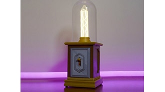
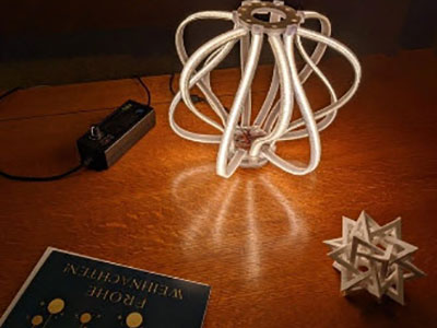
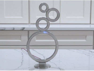
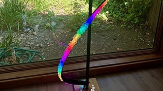
Check out this bendable, foldable lamp from Decktok. The four movable sections are filled with addressable RGBW lights and can be twisted, folded, or bent into any number of configurations. This is a really cool design!
The lamp ships with an onboard button for color changes, and can be controlled with the Tuya app right out of the box. The app features a number of nice animations, but not a lot of customization options. This guide will explain how to take it to the next level using an Adafruit Sparkle Motion controller. This adds WiFi connectivity and sound reaction using the Sparkle Motion's onboard microphone and the free, open-source WLED control app.
WLED allows you to create endless animations and color palettes, save presets and playlists for your lights, and comes with a number of customizable sound-reactive modes so your lamp can react to the music or ambient sounds in your environment.
This is a very easy project with just a little soldering and no coding. You get amazing control of your lights with just a few minutes' work. Plus, WLED is great at syncing up with other WLED controllers on the same WiFi network -- so you can make your top hat or Christmas tree lights dance in sync with your lamp in just a few clicks.
1 x USB-C Cable
- or - (depending on your USB ports)
A medium sized screwdriver
A soldering iron & accessories
Hot glue gun
We're using the existing wiring to the LED strip and the power supply, but replacing the controller with the Sparkle Motion board and adding our own pushbutton.
Solder the red and black wire from the lamp's power supply connector to VBUS (red) and GND (black) on the USB breakout.
Use the three center screw terminal connectors to connect to the three wires from the LED strip that's inside the lamp: black to G, yellow to 22, and red to +.
Connect one leg of your button to 18 and one to G on the Sparkle Motion. The button won't work if you use the screw terminal data pins -- they are output only.
This page will guide you through how to install WLED on the Sparkle Motion board.
The Sparkle Motion has a USB to serial chip which may need a driver installed before you can install WLED. Head over to the How to Install Drivers for WCH USB to Serial Chips tutorial, and download and install the new driver.
These next steps require a Web Serial-compatible browser. As of this writing, that means Google Chrome, Microsoft Edge, or Opera “desktop” browsers. Other browsers (Safari, Firefox, Explorer and anything mobile) won’t work.
Visit https://install.wled.me/
Plug your microcontroller into your computer with a known good USB cable. Click "Install" and select the port for your board.
Depending on the USB-to-serial bridge chip on the board, you might see one or two serial ports. On Mac, for instance, there might be both “/dev/cu.usbmodem[number]” and “/dev/cu.wchusbserial[number]”. Use the “wchusbserial” one.
After successful installation, enter your WiFi network name and password when prompted. This must be a 2.4 GHz WiFi network; ESP32 does not support 5 GHz networks. If it can’t connect, then as a fallback WLED will create its own 2.4 GHz WiFi access point.
If you don't see the "Connect to Wi-Fi" prompt, you'll need to set up your WiFi network using AP (access point) mode. Open up your WiFi settings and look for a WiFi network called WLED-AP. Connect to this network using the default password wled1234. The WLED interface will pop up in its own browser.
From here, go into Config/Wifi Settings and enter your WiFi credentials near the top. Give your project a name in the mDNS field a little further down the page. Now you can type in "projectname.local" (where "projectname" is your mDNS name) into any web browser on the same WiFi network to access your microcontroller.
You can also scan the QR code below to open access point mode.
For more help and troubleshooting tips visit the Getting Started page on the WLED knowledge base.
Head to the WiFi Setup screen under Config and create a good URL so you can control your project from any web-enabled device. Call it something you'll remember, that's easy to type into any web browser on your WiFi network in order to connect to your project.
In Safari or Chrome on your phone or computer, type in this web address to access the WLED interface: http://projectname.local (where "projectname" is whatever you put into this field).
Check out the Additional Settings page for more info on accessing your project. WLED has an "access point mode" that doesn't require a WiFi network for when you're out on the go. It's also helpful to download one of the WLED apps to help manage and organize your projects.
Next, head to the LED Preferences tab under the Config menu.
Scroll down to Hardware Setup. This lamp is using RGBW lights, so change the first field to SK6812/WS2814 RGBW.
For my lamp, the color order is BRG with Swap: W & G.
Set Length to 40 and set Data GPIO to 22.
Once you have all these settings correct your lamp will come on all in a warm yellow color. Once your lamp is connected to the board, if you have any other colors showing, mess around with these controls until you see yellow.
Scroll up just a bit to find this setting.
This lamp has a 12v 2a power supply, so we can safely limit the brightness to 2A (2000 mA) instead of the default of 850 mA.
Now you can use any computer or handheld device to control your LEDs.
Make sure your device is on the same WiFi network as your board. Navigate to your custom URL (projectname.local/ ) in a web browser. You'll see a color picker above a whole bunch of color palette choices.
Choose a color, choose an effect, and watch your lights animate and glow!
Save your favorite combinations as presets, create playlists, control the speed and intensity of the animations, and lots more. This web app is incredibly intuitive and easy to use.
Head over to the WLED wiki at https://kno.wled.ge/ to delve into all the particulars.
If your lights didn't come on, here are a few things to try:
Head back to WLED and check your pinout configuration under LED Preferences. Be sure the pin number is the correct GPIO for the attachment point you used.
Check your wiring! Be sure you connected to the IN end of the LED strip. These strips can be inconsistent, so this is a pretty common problem. Use an alligator clip to try connecting the data wire on the other end (the power and ground wires should work from either end).
Try re-uploading the WLED software.
If the lights come on but you can't control them: i.e. you type in "projectname.local" into your browser and it won't connect, make sure you're on the correct WiFi network. If you're on a different network than the one you set up the software on, you won't see the WLED connection.
If your lights came on in blue or green instead of yellow, your color order is wrong. See below to fix.
If only half your lights came on, be sure you've got the correct number in the "length" field under LED preferences.
If your lights came on in a variety of weird colors and looking like a 1950s diner interior, you may have the wrong LED strip type selected. RGBW strips and RGB strips are not the same, so be sure you've got the correct strip type, or you'll get very odd behavior.
If your microcontroller hangs or keeps rebooting, or gets really hot, you may have the power and ground lines switched. Unplug right away and check: this is a fast way to brick your controller.
The first step is to take a look at the power supply and find out what we're dealing with in terms of voltage. This power supply provides 12v, so we need a controller that can handle either 5v or 12v input. Using a board that's rated for 5v like most ESP32 boards will not work - your board will fry.
Luckily, Adafruit's got you covered. The Sparkle Motion board can easily handle 12v, and it's almost exactly the same size as the controller that ships with the lamp.
Find the slide switch on your Sparkle Motion controller and set it to the 12v setting.
Remove the rubber feet from the controller enclosure and unscrew the four screws. Carefully unsolder the five wire connections: red, yellow, and black to the LED strip connector and red and black to the power connector. Remove the controller.
Trim the solder blobs off the wires, while keeping them as long as possible. Strip a tiny bit of shielding off each wire.
Prep your momentary switch by soldering a short wire to each of the two legs on one side. Bend the legs outwards so the button can sit flat on the table. Trim off the other two legs to avoid accidental shorts. Cover the connections with heat shrink.
Solder all your connections as shown:
On the side with the power cord:
Red to USB breakout VBUS
Black to GND
On the side that goes to the lamp, use the middle 3 screw terminal ports:
Black to -
Yellow to 22
Red to +
For the switch:
One wire to GND or - (any pin or port will work)
One wire to pin 18
It's tempting to wire the switch to the screw terminal on pin 19 but the screw terminal pins are output only -- the switch will not work if wired to the screw terminal.
Squeeze a little hot glue into the indentation for the button on the bottom of the enclosure. The button is silicone so the glue won't stick -- this indentation will act as a mold for the glue. Press the top of your button into the wet glue, being careful not to get wet glue into the button mechanism. Now you have a perfectly shaped hot-glue cap for your button that will stay nicely in place inside the enclosure.
Now is the time for testing! First, double check that your voltage slider is set to 12v on the Sparkle Motion. Plug the two connectors in to the LEDs and the power supply. Your lights should come on in yellow. Click the button and the lights will cycle through different effects.
If this all happens, great! Move on to the next step to close up the case.
If not, check out the Troubleshooting section at the bottom of the page.
When using diagonal cutters below, ensure you have eye protection as tiny bits of plastic don't go well in eyes.
Place your button face down into the enclosure. Plug the USB breakout into the Sparkle Motion and nestle it all down on top of the button.
I used my flush cutter pliers to modify the case to make this all fit a little better, cutting out a few of the supports that were in the way of the board.
Replace the strain relief screws on the LED side. The USB breakout is in the way so we can't fix the strain relief screws on the power side. Add a zip tie or some glue if you're worried about the wires getting pulled out.
Sandwich the back of the case together on top of the Sparkle Motion and click the button a few times to make sure things are still aligned. Replace the four screws to close up the case as much as possible -- the Sparkle Motion is a little too tall to allow the case to close completely so you'll have a gap, but the screws still reach the holes -- it's a little inelegant, but it works!
If your lights come on in a weird white and purple flashing pattern, you have the wrong type of LED strip selected. Head to CONFIG / LED SETTINGS in WLED and change the LED type to SK6812/WS23814 RGBW.
If your lights come on in white or in any other color that's not yellow, you need to update the color order. Mine are BRG with a W & G swap. See the installation page for more info.
If only some of the lights come on, check to be sure you have the Length field set correctly -- my lamp has 40 lights.
If no lights come on, check to be sure you have the right GPIO set up. The middle terminal uses pin 22 -- if you used a different terminal, fix the GPIO number to match.
If your button doesn't work, check to be sure you set up the button GPIO in LED settings on pin 18, and double check the wiring -- the screw terminal ports won't read button clicks, you need to be connected to G and 18.
If your button still doesn't work, open the case and make sure it's aligned right. Try clicking the button when it's not in the case and see if that's the problem.
The Sparkle Motion comes with an onboard PDM microphone, so adding audio reactivity to your project is easy. Here's how to get it set up.
Click Config and then select the Usermods tab.
Scroll down a bit and you'll find the AudioReactive section.
Click the box to enable, then enter the settings and the Digitalmic section as follows:
Type: Generic I2S
Pin I2S SD: 25
Pin I2S WS: 33
Pin I2S SCK: 26
The other pins are unused.
Reboot your microcontroller for changes to take effect. That means either pressing the reset button or unplugging the board from power completely for a few seconds.
If you want the audio to work well in both loud and quiet settings, you may want to turn on AGC - automatic gain control. Start with Normal and then experiment with other options if you want more or less 'gain speed'.
There are a lot of other settings you can adjust in WLED. I found that the default settings for this mic seem to work perfectly, but you can delve into the particulars at https://kno.wled.ge/advanced/audio-reactive/
To use audio reactive mode, head back to the main interface and select any effect that has a music note icon next to the name. You can also search for musical-reactive effects that are built in.
Make some noise and see how your lights react. If it doesn't work, check your pins, try turning on AGC, tapping on the mic, and rebooting (removing power completely, waiting a few seconds then turn back on).
If you happen to have a 2D matrix as an output, the GEQ effect shows a 'binned' frequency response graph which can be good for debugging!
Once your lights are working, it's time for the fun part: creating light animations using WLED presets. This is easy and intuitive in WLED. Choose a color palette and an effect, then play with the sliders at the bottom of the Effect Mode column to customize the effect.
When you find something you like, click the +Preset button in the Presets tab and give your preset a name, then save it. You can reorder them using the "Save to ID" field.
You can create hundreds of presets using the preprogrammed effects, so take some time to play around and see what looks good on your LED strip.
Create at least 3 presets, and be sure they are saved to ID numbers 1-3. Our next step will be to set up the switch to toggle between these presets.
The WLED preset interface can also be used to send control commands to the LED strip. Once you've set up a button or switch, it can be used for a wide variety of control functions: change modes, change brightness, toggle the lights on and off, or a whole host of other features.
Each button function in WLED has 3 options: a short press, a long press, or a double press. I want my lights to cycle through presets with a short press, and to turn on or off with a long press. Here's how I set up a control preset for each of these features.
Click +Preset and then uncheck the "Use current state" checkbox. This will open up an API command window within the preset module.
Call the effect "Next_FX" and type {"ps":"1~3~"} into the API command box. This tells WLED to cycle through presets 1-3. If you'd like to cycle through more presets, change the 3 to the number of presets you have.
Be sure your preset IDs include all the numbers -- skipping a number will break this command.
Give your preset an ID number that's above the range of your preset numbers -- I called mine 9.
It's also possible to cycle between playlists. I made a playlist of sound reactive effects and a separate playlist of "standard" effects. I set up a preset that toggles between the two playlists -- effectively turning "sound reactive" mode on and off. I set this to space 11.
To turn the lights on and off, create another preset and call it "Toggle". Uncheck the "use current state" checkbox and enter T=2 into the API command box. This will tell the LEDs to toggle between on and off. Save this one to ID 10.
On the next page, these control presets will be connected to a button.
Find out more about creating these control presets here:
https://kno.wled.ge/features/presets/
You can enter either JSON commands or HTTP commands into this command box, giving you a lot of control over your WLED project.
https://kno.wled.ge/interfaces/json-api/
I soldered my button touch wire to pin 18.
In the LED Settings screen, scroll to the button setup section and set button 1 to use pin 18, with the type set as "Pushbutton".
I advise against using button 0. WLED's buttons have some default behaviors written in, and one of button 0's default behaviors is that when it's pressed for more than a few seconds, it resets your microcontroller to factory settings. I originally had button 0 selected, and I held the button down a bit too long while I was sewing it onto the hat, and .. POOF. All my settings and presets were wiped out.
Check out the "Backup" section under the Additional Settings page to learn to back up your configuration and presets, in case this kind of thing happens to you.
In WLED, the default actions for button 1 are designed to provide basic control without custom programming.
Button 1 Behaviors:
Short Press: Cycles to the next effect.
Long Press: Ramps brightness up/down.
Double Press: Cycles through color palettes.
Default State: If no custom macro is defined, the button defaults to these built-in functions, as outlined in the WLED documentation.
If you're happy with this, you're done! But if you want to take control of your button to do custom actions of your choosing, read on.
Head to the Time & Macros config screen. Scroll down to the Button actions area.
For button 1, enter the number assigned to the control presets you made on the last page. My Next_FX preset is number 9, so I entered 9 under "short press", and my Toggle preset is number 10 so I've got that set up as a "long press".
I also added the toggle mode that toggles between playlists to preset 11, so a double-click of my button will turn sound reactive mode on or off, since one of my playlists has sound reactive effects and the other doesn't.
If your button isn't working, here are some things to try:
Double check both the LED preferences page and the Time & Macros page to be sure your settings are correct and have saved.
Be sure your presets are correctly numbered. WLED gets confused if the presets have non-sequential IDs (so make sure they're numbered 1, 2, 3 rather than 2, 5, 7).
Be sure you're soldered to pin 18 on the Sparkle Motion -- the screw terminal pins will not read button presses.